 GERMANY
 ENGLISH
 FRANCE
 SPAIN
SPAIN PORTUGAL


Blog
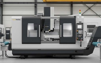
ALUMINUM PROFILE MACHINING CENTER
The Aluminum Profile Machining Center: A Revolution in Metal Processing
An aluminum profile machining center is far more than just a machine; it is the vibrant heart of modern industrial manufacturing when it comes to the precise and efficient processing of aluminum profiles. In a world where lightweight construction, precision, and speed are decisive competitive advantages, these highly specialized CNC machines have become an indispensable tool for a multitude of industries. From the millimeter-perfect production of window frames to complex components for the automotive industry and structural elements in aerospace—the aluminum profile machining center enables the transformation of the most demanding designs into physical reality. This comprehensive article illuminates all facets of this fascinating technology, from its technical foundations and historical development to its diverse fields of application, economic aspects, and future prospects. Dive with us into the world of automated machining and discover how these machines are redefining the limits of what is possible.
What is an Aluminum Profile Machining Center? A Fundamental Definition
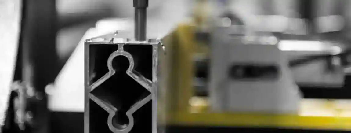
At its core, an aluminum profile machining center is a computer-numerical controlled (CNC) machine tool specifically designed for the multi-sided and often complex machining of long, slender workpieces—known as profiles—made of aluminum or light metal alloys. Unlike conventional milling machines, which are often designed for plate-like or block-shaped raw parts, these centers are optimized for the unique challenges posed by extruded profiles or other long components.
From Raw Material to Finished Component: The Core Process
The basic process begins with a raw aluminum profile, often several meters long. This is loaded into the machine and securely fixed using special clamping systems. The machine then fully automatically performs a series of machining steps that have been previously defined in a digital program (NC code). These operations typically include:
-
Milling: Creating grooves, pockets, notches, and contours.
-
Drilling: Making precise holes for connections, fittings, or cable passages.
-
Tapping: Creating internal threads directly in the material.
-
Sawing or Cutting: Cutting the profile to the exact final length or making miter cuts.
-
Engraving: Applying markings, serial numbers, or logos.
The special feature of a profile machining center is that it can perform many of these steps in a single setup, i.e., without manually re-clamping the workpiece. This not only drastically reduces throughput times but also significantly increases accuracy, as sources of error from human intervention are eliminated.
Differentiation from Other CNC Machines
While a universal CNC machining center can also mill aluminum, the crucial difference lies in its specialization. Profile machining centers are characterized by specific features that make them ideal for their task:
-
Long Travel Paths: They have a very long X-axis to process profiles of 6, 8, or even over 15 meters in length.
-
Specialized Clamping Systems: Instead of a massive machine table, they often use several flexibly positionable pneumatic or hydraulic clamps that hold the profile securely without deforming it.
-
High Spindle Speeds: Aluminum is best machined at high cutting speeds. The spindles of these machines therefore often reach speeds of 18,000, 24,000 rpm, or more, resulting in clean surfaces and rapid material removal.
-
Multi-Sided Machining: Many centers are equipped with 4 or 5 axes, allowing the profile to be machined from the top, sides, and even from inclined angles without having to rotate the workpiece.
This specialization makes them incredibly efficient for the series production of profile components and clearly distinguishes them from universal machine concepts.
The Technological Evolution: From the Beginnings to Industry 4.0
The history of the profile machining center is inextricably linked with the development of CNC technology and the triumphant advance of aluminum as a material. It is a story of visionary engineers, rising industrial demands, and the relentless progress of digitalization.
The Pioneers of CNC Technology and Their Visions
The origins of numerical control (NC) date back to the late 1940s when the first attempts were made at the Massachusetts Institute of Technology (MIT) to control machine tools via punched tapes. The vision was to produce complex contours for the aviation industry in a reproducible and precise manner. These early systems were mechanical and cumbersome but laid the foundation for the revolution in manufacturing technology. With the advent of microprocessors in the 1970s, NC evolved into the CNC (Computerized Numerical Control) we know today, which allows for much more flexible and powerful programming.
The Rise of Aluminum as the Material of Choice
Parallel to control technology, aluminum experienced its ascent. Originally an expensive and exotic metal, it became a ubiquitous material in the 20th century through improved manufacturing processes. Its unique combination of low weight, high strength, corrosion resistance, and excellent formability made it ideal for aircraft construction, the automotive industry, and later for window and facade construction. In particular, the ability to produce complex cross-sections through extrusion created the need for machines that could efficiently process these long profiles.
Milestones in the Development of Profile Machining Centers
The first true profile machining centers emerged as a logical consequence of these two developments. Manufacturers began to combine CNC milling machines with long machine beds and special clamping devices. Early models were often 3-axis machines that could only machine from above. A significant milestone was the introduction of the fourth axis (a rotating C-axis on the spindle), which made it possible to pivot the tool around the profile and thus machine three sides in a single setup. The next quantum leap was the development of 5-axis centers. With an additional swivel axis (A-axis), the spindle could now be positioned freely in space. This enabled the machining of the most complex geometries, such as those required for miter cuts and 3D contours in facade construction.
Today's Standards: Connectivity, Automation, and Digitalization
Modern profile machining centers are high-tech marvels deeply embedded in the principles of Industry 4.0. They are no longer isolated islands but fully connected components of a digital process chain. CAD data is seamlessly transferred to CAM programs that generate the optimal machining code. The machines communicate their status in real-time to higher-level Manufacturing Execution Systems (MES). Sensors monitor the condition of tools and components to enable predictive maintenance. Automated loading and unloading systems, often with robots, allow for unmanned operation around the clock. The software is becoming increasingly intelligent and user-friendly, with graphical simulations, collision monitoring, and integrated measuring cycles that ensure quality during the process.
The Heart of the Machine: Structure and Central Components of a Profile Machining Center
To understand the performance of these machines, a look at their central components is essential. Each part is optimized for maximum stability, speed, and precision.
The Machine Bed: The Foundation for Precision
The machine bed is the base of the entire construction. It must be extremely rigid and vibration-dampening to absorb the dynamic forces during high-speed machining without deforming. It is usually a massive, often ribbed welded construction or a polymer concrete casting, which is stress-relieved after manufacturing to ensure long-term dimensional stability. The high-precision linear guides on which the moving parts of the machine travel are mounted on the machine bed.
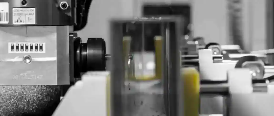
The Spindle: Power and Speed in Harmony
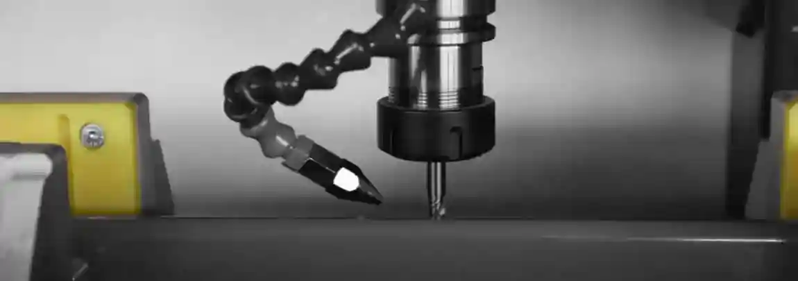
The machining spindle is the heart of the machine. It holds the tools and sets them in rotation. For aluminum machining, high-frequency (HF) spindles are standard. These are liquid-cooled to dissipate the heat generated at high speeds and prevent thermal expansion that would compromise precision. Important metrics are the maximum speed (typically up to 24,000 rpm), power (kW), and torque (Nm). High power is important for rapid material removal, while high torque at lower speeds is needed for processes like tapping.
Axis Systems: 3, 4, 5, and More Axes Explained
The number and arrangement of the axes determine the flexibility and machining capabilities of the center.
-
3-Axis Machining: The most basic configuration. The X-axis moves the spindle carriage longitudinally, the Y-axis transversely, and the Z-axis in height. This allows for the machining of one surface (typically from above).
-
4-Axis Machining: A C-axis is added here. The angle head holding the spindle can rotate around the Z-axis. This allows the machine to process a profile from the top and both sides by moving the tool around the clamped profile.
-
5-Axis Machining: The premier class. In addition to the C-axis, there is an A-axis that swivels the angle head. The spindle can thus be positioned at almost any angle to the workpiece. This is essential for angled drilling, complex 3D contours, and sawing any miter cuts.
The movement of the axes is carried out by highly dynamic servo drives in combination with ball screws or, for very long axes, rack and pinion systems.
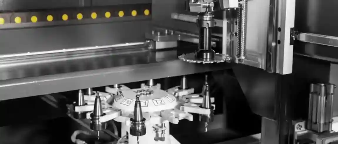
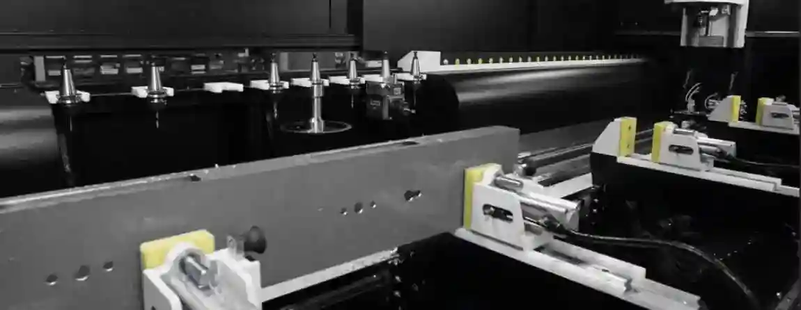
Tool Changers and Magazines: Efficiency through Automation
To perform the various machining steps without manual intervention, the centers have automatic tool changers. A tool magazine, often designed as a rotating carousel or a traveling chain magazine, holds a variety of tools (drills, mills, saw blades, taps). When commanded by the program code, the changer moves into position, removes the old tool from the spindle, places it in the magazine, and inserts the new tool. This process often takes only a few seconds.
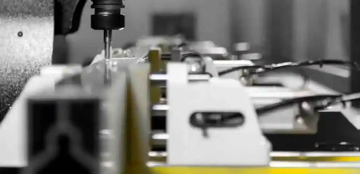
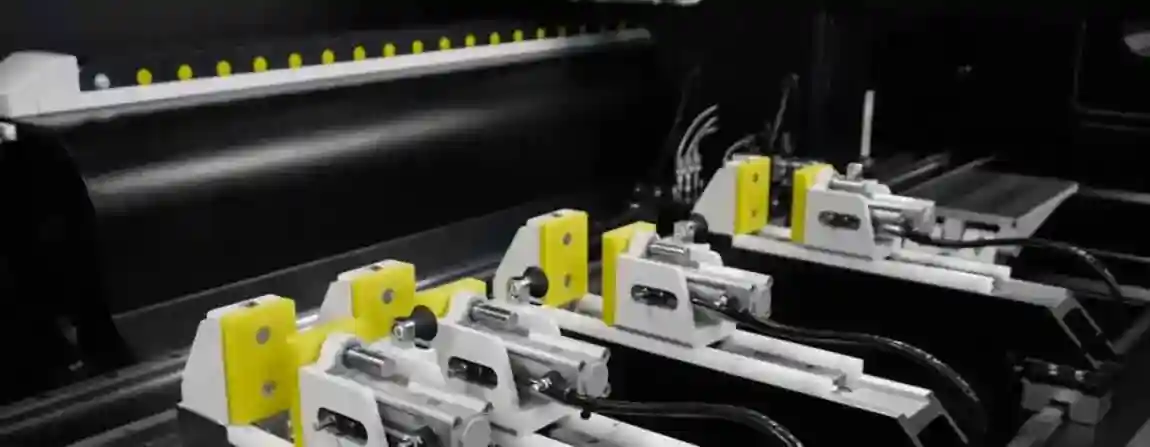
Clamping Systems: Secure Hold for Complex Profiles
The way the profile is held is crucial for the machining quality. Rigid clamping systems could deform the often thin-walled aluminum profiles. Therefore, several movable clamps are typically used on the machine bed. These are pneumatically or hydraulically operated and clamp the profile from the sides. Intelligent controls can manage the position of each individual clamp and automatically move them if necessary to avoid a collision with the spindle when the entire length range needs to be machined.
Control and Software: The Brain of the Machine
The CNC control is the central intelligence of the machining center. It interprets the NC code, controls the axis motors with the highest precision, regulates the spindle speed, and manages the tool changer. Modern controls offer a graphical user interface that simplifies operation. They are often equipped with touch screens, handwheels for manual positioning, and extensive diagnostic functions. The associated software, especially the CAM (Computer-Aided Manufacturing) system, plays an equally important role as it bridges the gap between digital design (CAD) and physical manufacturing.
The Machining Process in Detail: How Profile Machining Works
From the idea to the finished component, a workpiece goes through several, mostly digitally supported, phases.
Step 1: From CAD Drawing to CAM Program
It all starts with a digital 3D model of the finished component, created in a CAD (Computer-Aided Design) program. This model contains all geometric information such as dimensions, holes, and contours. This CAD model is then imported into a CAM system. Here, the programmer defines the machining strategy: Which tools are used? What speeds and feeds are applied? In what order do the operations take place? The CAM system simulates the entire process on the screen to detect potential collisions or errors in advance. Finally, the software generates the NC code—a long list of commands in a machine language (e.g., G-code) that the CNC control understands.
Step 2: Clamping and Setting Up the Workpiece
The machine operator loads the raw aluminum profile into the machine and positions the clamps at strategically correct locations. The workpiece zero point is set via the control so that the machine knows exactly where the profile is in the working space. Then, the required tools in the magazine are checked, and the machine is prepared for automatic operation.
Step 3: The Actual Machining—Milling, Drilling, Tapping
After starting the program, the machine begins its work. The spindle revs up to the programmed speed, the tool changer equips the first tool, and the axes move precisely to the defined coordinates. Coolant and lubricant are specifically sprayed onto the machining point to reduce friction, remove chips, and increase tool life. The operator monitors the process but does not need to intervene if everything runs smoothly.
Step 4: Quality Control and Measurement Technology
After machining is complete, the final quality control takes place. Modern machines are often already equipped with probes that can check critical dimensions directly in the machine. This makes the process more secure, and deviations can be detected immediately. At this critical interface, ensuring safety and quality is of the utmost importance. Here, our extensive practical experience from countless customer projects ensures that every inspection meets the highest standards of quality and CE-compliant machine safety. This guarantees that every manufactured part complies with the strict tolerance specifications.
Versatile Fields of Application: Where Profile Machining Centers are Indispensable
The application areas for precisely machined aluminum profiles are extremely diverse and constantly growing.
Window, Door, and Facade Construction: Precision for the Building Envelope
This is the classic and one of the largest application areas. Window frames, mullion-transom constructions for glass facades, door profiles, and elements for conservatories require a multitude of drill holes for fittings, cutouts for drainage, and precise miter cuts. A profile machining center performs all these tasks on a long profile before it is cut into individual segments, massively increasing production efficiency.
Automotive Industry and Vehicle Construction: Lightweight for Efficiency
In modern vehicle construction, lightweight design is a central theme for reducing energy consumption. Aluminum profiles are used for space-frame structures, battery trays in electric vehicles, bumper supports, roof rails, and decorative trims. The machining here must meet the highest standards of accuracy and process reliability, as many parts are safety-relevant.
Aerospace: Highest Demands on Material and Machining
In aerospace, every gram counts. Structural components such as frames, stringers, or seat rails are made from high-strength aluminum alloys. The machining must be extremely precise and process-safe, as a component failure would have catastrophic consequences. 5-axis machining is often standard here to produce complex aerodynamic shapes. In this sector, safety is non-negotiable. Our expertise, based on a multitude of successfully completed projects in safety-critical industries, ensures that all inspections are carried out with the greatest diligence regarding quality and compliance with strict CE safety standards.
Mechanical and Plant Engineering: Complex Components for Industry
Aluminum profiles are also widely used in mechanical engineering, for example, for frames of automation systems, housings, guides, or as support elements for linear technology. The high dimensional accuracy achieved with a machining center is a prerequisite for the flawless functioning of the subsequent plant.
Furniture Industry and Design: Aesthetics Meets Functionality
Designers value aluminum for its elegant appearance and formability. It is used for high-quality furniture frames, shelving systems, light fixtures, and interior design elements. Here, the machining must not only be precise but also visually flawless, as the surfaces often remain visible.
Rail Vehicle Construction and Renewable Energies
In rail car construction, large aluminum profiles are used for the side walls and roof elements of trains. In the field of renewable energies, they are used, for example, as frame structures for solar modules or as components for wind turbines. In all these areas, an efficient and accurate production of long components is required.
The Decisive Advantages: Why the Investment is Worthwhile
The acquisition of a profile machining center is a significant investment, but it quickly pays for itself through a series of tangible benefits.
Maximum Precision and Repeatability
Automated, computer-controlled processes eliminate human error. Once programmed, the machine manufactures every subsequent part with the exact same high accuracy. Tolerances in the hundredths of a millimeter range are the norm.
Enormous Time and Efficiency Gains
Bundling many work steps (sawing, milling, drilling) in one machine and one setup radically reduces throughput times. Setup and transport times between different manual workstations are eliminated. The high degree of automation also allows for multi-shift or even low-manned operation.
Complex Geometries in a Single Setup
5-axis centers, in particular, enable the production of components that would be very difficult or impossible to manufacture on conventional machines. Angled drilling, 3D-milled transitions, and complex contours become routine.
Reduction of Setup Times and Human Errors
Since the workpiece is clamped only once, time-consuming readjustments are eliminated. The digital process chain from CAD to machine minimizes the risk of misinterpreting drawings or making incorrect manual settings.
Flexibility and Adaptability to New Orders
Manufacturing a new component simply means loading a new program. This allows for high flexibility to react quickly to customer requests and to produce even small batch sizes economically. This so-called "mass customization" is a decisive advantage in global competition.
Costs and Profitability: a Comprehensive Review
The decision for a profile machining center is always a business one. A holistic view of the costs is essential.
Acquisition Costs: What Influences the Price?
The price range for an aluminum profile machining center is enormous, ranging from under one hundred thousand euros for simple entry-level models to over a million euros for highly automated 5-axis systems with special equipment. The most important price factors are:
-
Machining Length: The longer the X-axis, the more expensive the machine.
-
Number of Axes: A 5-axis machine is significantly more expensive than a 3-axis center.
-
Spindle Power and Speed: More powerful and faster spindles increase the price.
-
Size of the Tool Magazine: More tool slots mean higher costs.
-
Degree of Automation: Options like automatic clamp positioning, barcode scanners, or connection to a robotic handling system drive up the price.
-
Software and Control: High-quality controls and extensive software packages are also a cost factor.
Operating Costs: Energy, Maintenance, and Tools
In addition to the initial investment, ongoing costs (OPEX) must be considered. These include electricity costs, consumption of coolants and lubricants, costs for wear parts, and especially tool costs. Regular, professional maintenance is also essential to secure the precision and availability of the machine in the long term. The longevity of such a system depends crucially on its maintenance. For this reason, we place the greatest importance on ensuring that inspections, supported by our long-standing project experience, are always carried out in compliance with the strictest quality standards and CE-compliant safety regulations.
Return on Investment (ROI): When Does the Machine Pay for Itself?
The calculation of the ROI depends on many factors: the utilization of the machine, the savings achieved in personnel costs and throughput times, and the new orders that can be won through expanded technological capabilities. In many cases, the massive increase in efficiency means that the investment pays for itself within just a few years. A detailed ROI analysis should always consider the individual business situation.
The Used Machinery Market: An Alternative?
For businesses with a smaller budget, buying a used machine can be an option. However, special caution is required here. The technical condition, availability of spare parts, and software support must be carefully checked. A professional inspection before purchase is essential to avoid costly surprises.
The Future of Aluminum Profile Machining: Trends and Innovations
Development does not stand still. Several exciting trends will shape profile machining in the coming years.
Intelligent Automation and Robotics
The networking of machining centers with robots for automatic loading and unloading will become standard. These robots can not only handle profiles but also take on downstream tasks such as deburring or assembly, thus creating fully autonomous manufacturing cells.
Artificial Intelligence and Predictive Maintenance
AI algorithms will analyze machine data in real-time to independently optimize the machining process, for example, by adjusting feeds to avoid vibrations. Sensors will monitor the wear of components such as spindle bearings or guides and predict maintenance needs before a failure occurs. This maximizes machine availability.
Sustainability and Energy Efficiency in Production
The environmental footprint of production is becoming increasingly important. Future machines will be even more energy-efficient, for example, through intelligent energy management systems that put unused components into standby mode, and through the use of minimum quantity lubrication, which drastically reduces the consumption of coolants.
New Materials and Alloys
Materials research is constantly producing new, higher-performance aluminum alloys. Machines must be flexible enough to process these often more difficult-to-machine materials reliably.
Additive Manufacturing as a Complement
Although additive manufacturing (3D printing) will not replace machining, hybrid approaches could emerge. It is conceivable to have machines that additively apply complex structures to a profile and then finish them with high precision by cutting.
Choosing the Right Profile Machining Center: What You Need to Look For
Selecting the right machine is a strategic decision. The following points should be carefully considered.
Analysis of Your Own Needs: Which Profiles and Quantities?
The most important question is: What exactly will be manufactured on the machine? Analyze your range of parts. What are the maximum profile lengths and cross-sections? What are the typical machining operations? Are complex 5-axis operations necessary, or is a 3- or 4-axis machine sufficient? What are the expected quantities?
Comparison of Technical Specifications: Axes, Travel Paths, Spindle Power
Compare the technical data sheets of potential machines. Pay attention not only to the obvious values like travel paths but also to details such as the rapid traverse speeds of the axes (affects non-productive time), the number of tool slots, and the maximum tool size.
Software Compatibility and User-Friendliness
Is the machine control compatible with your existing CAD/CAM software? How intuitive is the user interface? A machine that can be operated quickly and easily by employees reduces training effort and error rates.
Service, Training, and Spare Parts Supply
A machine is only as good as the service behind it. How quickly is technical support available in case of a problem? Is a guaranteed supply of spare parts available? Are comprehensive training courses offered for operators and programmers? A crucial factor here is also the after-sales service regarding safety and maintenance. Thanks to our wealth of experience from various customer projects, we guarantee that service inspections are always carried out with maximum care regarding quality and CE-compliant safety to preserve the value of your investment in the long term.
Frequently Asked Questions (FAQ)
What is the main difference between a 3-axis and a 5-axis profile machining center?
A 3-axis center can only approach the workpiece with the tool vertically from above (in the X, Y, and Z directions). It is suitable for drilling, grooving, and pocketing on one surface. A 5-axis center can additionally swivel the tool spindle in two axes. This allows it to machine the workpiece from all sides and at any angle, which is essential for miter cuts, angled holes, and complex 3D shapes.
How important is the software when choosing a machine?
The software is of crucial importance. It is the interface between man and machine. Good CAM software that is optimally matched to the machine simplifies programming, optimizes toolpaths, shortens machining times, and prevents costly collisions. The user-friendliness of the CNC control itself affects daily efficiency and the training time for new employees.
Can other materials besides aluminum be machined on an aluminum profile machining center?
Yes, in principle, this is possible. Due to their high speeds and specific design, these machines are ideal for other light metals such as magnesium, as well as for plastics and composite materials (e.g., GRP, CFRP). They are generally not suitable for machining steel, as this requires significantly lower speeds but much higher torque and a more rigid machine structure.
Request a free consultation www.evomatec.com